For those of you who, just as me, are bothered with the bad composite video output of the Amiga 600/1200 I may have found a very effective upgrade. For some time I have wondered why the output lately seemed to be getting significantly worse as years went by. At first I thought it was just never monitors that had bad analog video circuitry compared to older ones but recently I definitely noticed a significant degrading in video output on my machines.
The big plague that is tormenting all of these machines are the leaking electrolytic capacitors. They have come to an age now where generally all of hem are affected and must be dealt with as soon as possible to no be destroyed from within! The replacement of capacitors are an absolute necessity but it's something I won't cover in this article. There are plenty of existing guides out there already. At first a thought that this whole capacitor situation was to blame for the picture degradation but after re-capping two PAL Amiga 600 machines without any obvious improvement in the video output, in fact the re-capping actually made things worse, I began to wonder what was really going on. Both machines eventually started having problem with the reg/green color phase and color flickering. A common problem when the color delay is acting up. Remember, PAL inverts the color phase on every other line and if that phase is unstable it will result in color flickering.
This red/green flickering situation got me wondering about how the video encoder chip in the Amiga 600 actually worked. It uses the CXA1145 chip by Sony. The same chip is used in many other consumer equipment and video game consoles from around that time. The CXA1145 design relies on two specifically delicate external components. One delay line and one band pass filter. Those were my primary suspects. In the Amiga 600 design they are called Z221 and Z222. The datasheet is pretty vague regarding these components. It mentions that the BPF should be centered around 4.43MHz for PAL and 3.58 MHz for NTSC, the color carrier frequencies, and the delay line should be 180ns in both cases.
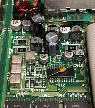
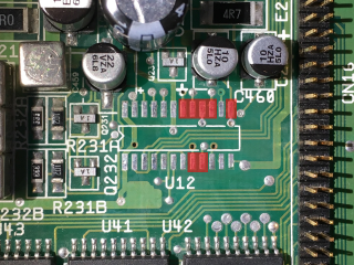
This is a picture over the area covering the video encoder circuit of an Amiga 600. Commodore did not use the filter and delay line mentioned in the CXA1145 datasheet but instead some other ones (the rectangular shaped RF cans on the left side of the picture). Actually the delay line consists of three cans connected together in serial and the band pass filter is a single can. I have not managed to properly identify them nor source new ones and they are pretty tricky to de-solder so I would rather avoid that. On both the Amiga 600 I recently restored I had to clean the area around Z221 and Z222 thoroughly to get rid of the leaked-out and corrosive capacitor electrolyte. In the picture above the area has been cleaned and all electrolytic capacitors replaced.
I suspect my thorough cleaning is part of what quickly worsened my video problems. My theory is that Z221 and Z222 cans are sensitive to various cleaning detergents. In my case I think my use of isopropyl alcohol in the area is to blame. I could clearly see the picture degrading after cleaning. The components Commodore used for Z221 and Z222 filter and delay line may not be aging gracefully and are not robust enough to survive a leaky capacitor and cleanup. In fact I suspect the leaking capacitor electrolyte itself may even deteriorate the Z221 and Z222. They have a typical RF can style construction with an open bottom against the PCB. Any fluids on the PCB will effectively move up into the can because of the capillary force.
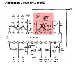
This got me thinking about a possible replacement for the Amiga 600/1200 analog video section. Preferably a solution that would fit inside the case and one that also had to be fully reversible. This turned out to be easier than I initially thought! The diagram above is taken from the CXA1145 datasheet and shows the example circuit suggested by Sony and is basically the same design used by Commodore in the Amiga 600/1200. The bandpass filter and delay line are marked with red.
Sony made an updated video encoder chip named
CXA1645 that is almost pin-compatible with the CXA1145 and it does not depend on external bandpass filter and delay line! Instead those pins are used to provide a real S-video output.
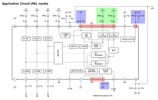
This is the suggested CXA1645 circuit from the datasheet. Very similar to the CXA1145. I have color coded the main differences.
Red - pins with new function compared to existing circuit
Blue - new or altered components
Green - S-video output
The changes required compared to the original circuit is pretty small. What I did was to remove the old CXA1145, replace it with a new CXA1645 and piggy-back the new and changed components around it. Worth mentioning in this case is that the CXA1145 has an audio buffer between pins 8 and 9. Those pins have other functions on the CXA1645, thus the audio to the RF modulator is lost by doing this mod. To me that was no issue but if you really want to keep the RF modulator audio working you could probably just bridge pins 8 and 9 together on the back of the PCB in order to restore that function.
DISCLAIMER: This is NOT a beginners modification. It requires proper equipment and good surface mounted soldering skills. Make sure you know what you are doing and if in any doubt, leave it to someone who have the proper skills and tools. These computers are not made any more and are only getting fewer and fewer. Do not take any chances. This is only a documentation of what I did. I can not be held responsible for any eventual damages you may cause by performing this modification yourself.
 Step one
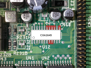
 - Removal of the CXA1145.
 Step two
 - Isolate changed pins with kapton tape. Placement of tape marked in red.
 Step three
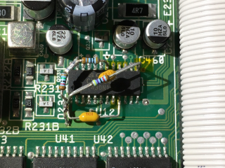
 - Solder the new CXA1645 on top.
 Step four
 - Add components. The 1% 16k resistor between pin 18 and ground sets the color signal amplitude. I only had 5% resistors so I used one 15k and one 1k i series and measured a few samples using a calibrated LCR mater until I got well within the 1% mark.
 Step five
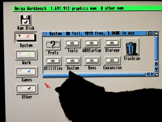
 - Annoy cat with fine picture and colorful mouse pointer.
This has been a very successful modification. The picture is really good now. Better than I can remember it ever was and this is only composite video. Next step is to explore the possibilities with the CXA1645 S-video output. This modification was performed on an Amiga 600 but should be more or less the same for Amiga 1200 as well.